
|
Failure Analysis & Durability Improvement |
|---|
|
|
Failure Analysis & Durability Improvement |
|---|
|
Home Page |
Bearings | Gears | Electronics |
Contact Us |
|---|
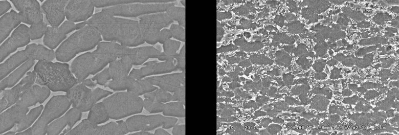
Different Heat Treatment Yields Different Microstructures of the Same Material |
|---|
Fatigue | |
|---|---|
|
Fatigue is the failure of a component due to repeated loading & unloading.
Each loading & unloading is called a cycle.
The simplest demonstration of fatigue is take a paper clip, straighten it out,
and then bend it back & forth.
You'll probaly cause failure fairly quickly.
It has been estimated that 90% of engineering failures are due to fatigue.
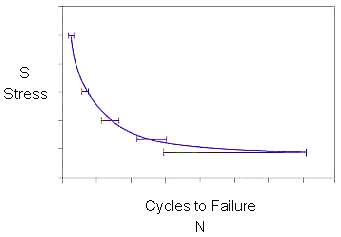
Factors influencing fatigue life include the stress range and the R ratio. The R ratio is defined as the minimum stress divided by the maximum stress. For exmaple, if the stress is cycled between -50 and 50 ksi, the stress range is 100 ksi and the R ratio is -1 (-50/50). Half of the stress range is called the alternating stress, which in this case would be 50 ksi. Two common R ratios are -1, which is often referred to as "Fully reversed" and 0, often called "Zero to Max". Not surprisingly, the greater the stress range, the shorter the fatigue life. If fatigue life is plotted against stress range, we get something like the curve to the left. This is called an S-N curve, since it relates stress range (S) to cycles (N). Typically, the Y axis is linear while the X-axis is logrithmic. Note that the slope of the curve decreases as life increases. Some materials have what is called an "Endurance limit" or "Fatigue limit". In these cases, the curve goes flat, and there is a stress range below which the material will never fail, no matter how many load cycles are applied. S-N curves are also influence by R ratio. The higher the mean stress, the lower the fatigue life. If we plot S-N curves with different R ratios, we get something like this: |
Even when designed by top-flight engineers,
fatigue failures may come about for a number of reasons:
|
|
Overload | |
|
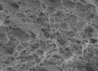
Overload occurs when a section of a component is so highly loaded that the materials ultimate tensile strength (UTS)
is exceeded.
The fracture surface exhibits what is commonly referred to as "cup and cone" appearance, as shown in this photograph.
This type of failure is not very commom, since it only happens when something goes terribly wrong, such as:
|
Corrosion | |

|
Corrosion is the attack on a component by a chemical reaction with its environment.
One of the most common examples is rusting of iron or steel,
which is caused by iron chemically reacting with oxygen,
and can be significantly increased by the presence of water.
Corrosion occurs at the surface,
where both the component and its environment come into contact.
The simplest way of combatting corrosion is to put a barrier in place to
separate the two,
such as paint or a coating of zinc.
Some metals are more resistant to corrosion than others.
Aluminum, like iron, reacts with oxygen to form an oxide.
Unlike iron, the oxide layer on aluminum adheres tightly to the surface & inhibits further oxidation,
instead of flaking off and allowing corrosion to penetrate deeper into the component.
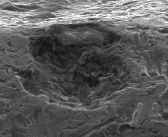
Since corrosion is a chemical process, it attacks the different constituents of the microstructure at different rates. Corrosion damage will show some microstructural features (Those more resistant to corrosion) remaining while those around it are gone. This is shown in the pit on the left of the photo below, where there are some white ridges remaining while the material around it has been removed. Contrast that with the pit on the right which due to erosion, a mechanical process. |
Erosion | |
|
Erosion is a mechanical process where small particles are blasted against a component removing material. Rather than selectively removing portions of the microstructure as in corrosion, it removes whatever it hits, leaving a smoother surface, like the one shown to the left. A good example of a component subjected to erosion would be blades on a helicopter operating in the desert. When the chopper comes in to land, the downdraft kicks up a lot of sand particles. The blades, which are rotating rapidly, have many high speed impacts with these particles. |
|
|
Failure Analysis & Durability ImprovementContact: Ed Pope 317-750-3414 Ed@Failure-Analysis-Durability.com |
Copyright © 2014
VEXTEC |
| About Us | Privacy Policy | Terms of Use |